UG NX三维机械设计及三维标注(3D Mechanical Design and 3D Annotation Using UG NX)(英文版)
书 号:9787113254162
丛 书 名:普通高等教育“十三五”规划教材
作 者:张瑞亮
译 者:
开 本:16开
装 帧:平装
正文语种:中文
出 版 社:中国铁道出版社有限公司
定 价:39.8元


-
内容简介
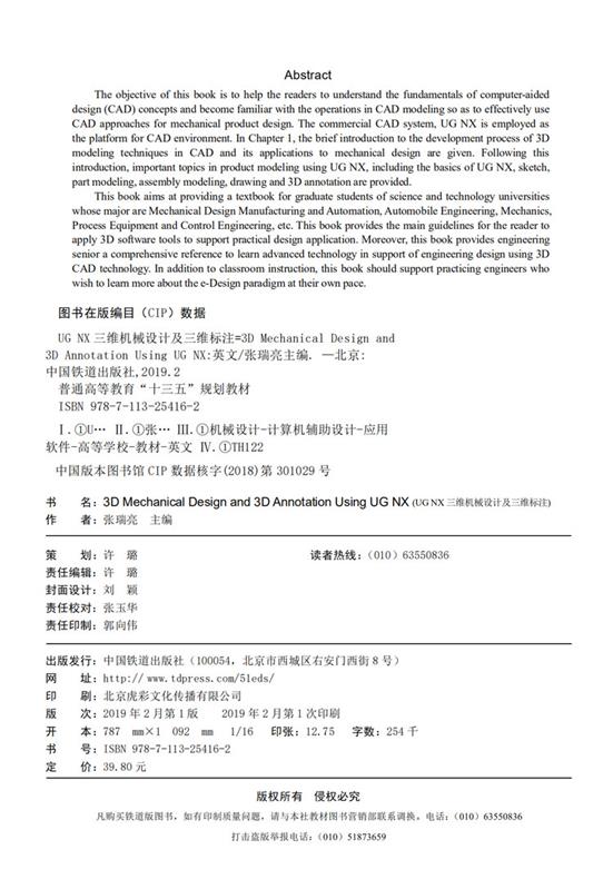
The objective of this book is to help the readers to understand the fundamentals of computer-aided design (CAD) concepts and become familiar with the operations in CAD modeling so as to effectively use CAD approaches for mechanical product design. The commercial CAD system, UG NX is employed as the platform for CAD environment. In Chapter 1, the brief introduction to the development process of 3D modeling techniques in CAD and its applications to mechanical design are given. Following this introduction, important topics in product modeling using UG NX, including the basics of UG NX, sketch, part modeling, assembly modeling, drawing and 3D annotation are provided.
This book aims at providing a textbook for graduate students of science and technology universities whose major are Mechanical Design Manufacturing and Automation, Automobile Engineering, Mechanics, Process Equipment and Control Engineering, etc. This book provides the main guidelines for the reader to apply 3D software tools to support practical design application. Moreover, this book provides engineering senior a comprehensive reference to learn advanced technology in support of engineering design using 3D CAD technology. In addition to classroom instruction, this book should support practicing engineers who wish to learn more about the e-Design paradigm at their own pace.
本书的目的是帮助读者了解计算机辅助设计(CAD)概念的基本原理,并熟悉CAD建模中的操作,从而有效地利用CAD方法进行机械产品设计。在商用CAD系统中,采用了UG NX作为CAD环境的平台。第一章简要介绍了三维建模技术在计算机辅助设计中的发展过程及其在机械设计中的应用。之后,介绍了使用UG NX进行产品建模的重要课题,包括UG NX的基础知识、草图、零件建模、装配建模、绘图和3D注释。
本书旨在为机械设计、制造和自动化、汽车工程、机械、工艺设备和控制工程等专业的科技类大学研究生提供教材。此外,本书还为工程专业毕业生提供了学习先进技术的参考,以支持3D CAD技术的工程设计。 -
前言
With the development of science and technology and the globalization of the economy, traditional manual design is gradually being replaced by computer aided design (CAD). The application of computer technology in product design has evolved from the calculation and drawing in the past to the integration of today’s 3D modeling, optimization design and simulation, which greatly shortens the design and manufacturing cycle of the product and improves the design quality.
The machinery industry plays a pivotal role in the entire industrial production process. Mechanical CAD is of great significance to promote the development of the machinery industry and the improvement of the level of science and technology. With the continuous improvement of China's manufacturing informatization level, the demand for high-level talents in the machinery industry who are familiar with both professional knowledge and 3D CAD technology is becoming more and more intense. Therefore, in the preparation of this book, we strive to reflect the contemporary mechanical 3D CAD. The basic content and development level, focusing on the basic content of mechanical CAD technology and the application of 3D CAD technology.
This book uses UG NX software as a 3D CAD platform. It mainly introduces the basic content and development history of mechanical CAD technology, UG basic knowledge, sketching, 3D modeling and typical mechanical parts modeling, assembly design, engineering drawings and product manufacturing information (PMI). This book takes the design of the planetary gear reducer as the main line. While introducing the UG command and function, it also introduces the ideas and methods of the typical parts and assembly design of the reducer. In the process of learning, readers can not only master the concept of CAD, the commands and functions of UG, but also know well about the methods and steps of engineering design using 3D CAD.
As a combination of theory and practice, the content is easy to understand. The main functional commands are explained with the operation examples step by step, so that beginners can apply learning commands to specific design. This can more effectively stimulate readers’ interest in learning and improve learning effect. The book was written by the College of Mechanical and Vehicle Engineering of Taiyuan University of Technology, and Zhang Ruiliang was the editor. Zhang Ruiliang wrote Chapter 1 and Chapter 4; Ding Hua wrote Chapter 2 and Chapter 5; Yao Aiying wrote Chapter 3; Xin Yupeng wrote Chapter 6; Liu Feng wrote Chapter 7. The entire book was organized by Zhang Ruiliang, and Xin Yupeng reviewed the manuscript.
We are thankful to graduate students, Muhammad Yousaf Iqbal Rao and Anuj Desaihave, for their friendly help in the process of writing this book. At the same time, the book refers to a large amount of literature and materials, and we would like to express our deep gratitude to the original author. Due to the limited editorial level, there might be certain inadequacies or mistakes in the book and we sincerely hope that readers will criticize and correct.
Example files and slides needed for this book made by authors from College of Mechanical and Vehicle Engineering of Taiyuan University of Technology are available and could be obtained by author’s e-mail (rl_zhang@163.com).
Written at Taiyuan University of Technology
2018-11-20 -
目录
Chapter 1 Introduction to CAD in Mechanical Engineering 1
1.1 Development History of CAD Technology 1
1.1.1 Wireframe models 2
1.1.2 Surface models 3
1.1.3 Solid models 4
1.1.4 Parametric solid model 5
1.1.5 Variational modeling technology 6
1.1.6 Direct modeling and synchronous modeling techniques 7
1.2 Application of CAD Technology in Mechanical Design 9
1.2.1 Influence of 3D CAD technology on mechanical design 9
1.2.2 Basic functions of CAD system 10
1.2.3 CAD Data exchange standard 11
1.3 Questions and Exercises 13
Chapter 2 Basics of NX 15
2.1 The User Interface of NX 15
2.1.1 Start and exit NX 12.0 15
2.1.2 User interface 16
2.1.3 Customizing the user interface 18
2.2 Basic Operations of NX 20
2.2.1 File operations 20
2.2.2 Layer operations 23
2.2.3 Object operations 25
2.2.4 Mouse operation 28
2.2.5 View operations 29
2.2.6 Working coordinate system 37
2.3 Exercises-basic Operations of NX 44
2.4 Questions and Exercises 47
Chapter 3 Sketch 50
3.1 Sketch Overview 50
3.1.1 The Basic Concept of Sketch 50
3.1.2 Sketch Preference 52
3.1.3 Create Sketch Plane 53
3.2 Sketching 54
3.2.1 Sketch Point 54
3.2.2 Profile 55
3.2.3 Rectangle 56
3.2.4 Arc 57
3.2.5 Circle 57
3.2.6 Studio Spline 58
3.2.7 Derived Lines 59
3.2.8 Quick Trim 60
3.2.9 Quick Extend 61
3.2.10 Fillet 61
3.2.11 Chamfer 62
3.3 Constraints 63
3.3.1 Basic Concept of Constraints 63
3.3.2 Geometric Constraints 64
3.3.3 Sketch Dimensions 65
3.3.4 Show/Remove Constraints 66
3.3.5 Convert To/From Reference 66
3.3.6 Alternate Solution 67
3.4 Exercise-Sketch Example 67
3.5 Questions and Exercises 71
Chapter 4 Part Modeling 73
4.1 Feature Modeling Overview 73
4.1.1 Common modeling methods 73
4.1.2 Feature-based modeling process 75
4.1.3 Feature type 76
4.2 Boolean Operations 77
4.3 Basic Features 81
4.3.1 Extrude Features 81
4.3.2 Revolve Features 84
4.3.3 Sweep along Guide 84
4.4 Placement of Engineering Features 87
4.4.1 Placement Face 87
4.4.2 Horizontal Reference 87
4.4.3 Positioning methods 88
4.5 Datum Features 89
4.5.1 Datum Plane 89
4.5.2 Datum Axis 90
4.6 Exercises - Feature Modeling 91
4.7 Modeling of Typical Mechanical Parts 93
4.7.1 Modeling of gear shaft 93
4.7.2 Modeling of case part 99
4.8 Exercise - Cylinder Gear Shaft 108
4.9 Questions and Exercises 111
Chapter 5 Assembly Modeling 117
5.1 Assembly Overview 117
5.1.1 Basic process of NX assembly modeling 117
5.1.2 Terms in NX assembly 118
5.1.3 Introduction to the assembly interface 119
5.1.4 Assembly Navigator 120
5.1.5 Reference set 124
5.2 Assembly Method 124
5.2.1 Bottom-up assembly modeling 124
5.2.2 Top-down assembly modeling 126
5.3 Assembly Constraints 129
5.3.1 Constraint status 129
5.3.2 Fix 130
5.3.3 Touch Align 130
5.3.4 Distance 132
5.3.5 Concentric 132
5.3.6 Center 132
5.3.7 Angle 133
5.3.8 Parallel and Perpendicular 133
5.3.9 Fit and Bond 133
5.3.10 Align/Lock constraint 134
5.4 Component Edit 134
5.4.1 Mirror 134
5.4.2 Pattern 137
5.5 Exploded Views 139
5.5.1 Create exploded views 139
5.5.2 Unexplode component and Delete explosion 141
5.6 Assembly Interference Check 142
5.7 Exercise - Planetary Reducer Output Shaft Assembly 142
5.8 Questions and Exercises 147
Chapter 6 Drafting 149
6.1 Introduction to Drafting 150
6.2 Drafting Preferences 151
6.3 Drafting Management 151
6.3.1 The 1st angle projection and the 3rd angle projection 152
6.3.2 Creating a new drawing 153
6.3.3 Edit/Open/Delete sheet 155
6.4 Drafting Views 156
6.4.1 Base view 156
6.4.2 Projected view 156
6.4.3 Detail view 157
6.4.4 Section view 158
6.4.5 View break 163
6.5 Edit Drafting View 163
6.5.1 Setting dialog box 163
6.5.2 Section line and hinge line 164
6.5.3 Non-sectioned component 164
6.6 Drafting Annotations 165
6.6.1 Centerlines 165
6.6.2 Note 166
6.6.3 Geometric dimension and tolerancing in drafting 167
6.6.4 Assembly drawing 169
6.7 Exercise-Drafting Example 173
6.8 Questions and Exercises 176
Chapter 7 Product and Manufacturing Information 178
7.1 Configuration 178
7.2 Creating PMI 181
7.2.1 PMI annotation plane 181
7.2.2 PMI associated objects 181
7.2.3 Sizing PMI 182
7.3 Dimensions 183
7.3.1 PMI dimensions 183
7.3.2 Converting feature dimensions to PMI 185
7.3.3 Tips for using dimensions 185
7.3.4 PMI hole callouts 186
7.4 Annotations 187
7.4.1 Note 187
7.4.2 Feature Control Frame 187
7.4.3 Datum Feature Symbol 187
7.4.4 Datum Target 188
7.4.5 Surface Finish 188
7.4.6 Weld Symbol 188
7.4.7 Balloon 189
7.5 Section View 189
7.6 Exercise-PMI Example 190
7.6.1 Add PMI to a 3D model 190
7.6.2 Create a PMI section view 194
7.7 Questions and Exercises 195
References 196 -
作者介绍
张瑞亮,副教授,太原理工大学齿轮研究所,教授三维机械设计等课程,主编与参与编写教材多部,拥有三维标注软件、线缆快速设计系统软件、自卸车设计平台软件等多个软件著作权。 -
编辑推荐
本书为英文版本,适合双语教学,并根据全三维设计的发展趋势和现状,特别增加了三维标注的相关内容。 -
书评书荐
-
附件下载
图书推荐